Wimax transmit power calculation  

Do we need to consider return loss of the device along with insertion loss when we calculate the output power of the particular device?

For example Balun has return loss of 12dB and IL of 2.5 dB, when i give input to the balun as 0dBm what will be the out put of the balun power available?
output power= Input power-IL or
output power= Input power-(IL+RL)?

In such case if the input to the BALUN is 0dBm then the output of the Balun will be -15dBm because of the return loss 12 dB and insertion loss 2.6dB, Is this calculation correct?

If there is really a 12 dB return loss in the balun then the calculation is correct.

Iam just wondering why the RL of the Balun is 12dB. I think it is quite large. We use balun to match impedance and minimize RL.

Can you tell how the value of RL obtained?

Do not consider the return loss when making your link budget or EIRP calculations. The insersion loss is to be considered (only).

The return loss is the indicator of the health of your cable and antenna together. The antenna is an impedence matching device from the cable (50 ohms) to free space (377 ohms) and is frequency dependant.

Since there is no perfect impedence match there will be some reflected power. A return loss of 13 db means that 1/20 th of the power was reflected. If you were transmitting 10 watts than .5 watts was refected. This number is too little to worry about.

However, if you see reflected power start to rise you must ceck your cable and antenna and jumpers.

i over looked return loss as loss due to return instead of loss of the return. thats why i think its value is high for a loss.

to consider it theoretically in your calculation. just subtract the linear value of RL form 1 then convert it back to dB

for 12dB RL means 1/16 of incident is reflected hence 15/16 is for the load (1-1/16)

So your loss due to return is 10log(15/16)= - 0.28dB

[get this widget]

Read More...
AddThis Social Bookmark Button

Importance of the transmittig antenna gain for the Base station  

As per my RF design i am getting +40dBm Tx power at the antenna port after subctracting the insertion loss and Returm loss of Balun and TDD switch, the same Power(+40dBm)is fed to TX directional antenna, My Question is ,Will the TX Antenna gain(G) would help to increase radiated power more than 42dBm?

Please help me in understanding more on the inportance of antenna Gain(G)?

Forward power consists of transmit power minus cable and connector loss, minus combiner loss (if applicable) plus atnenna gain (in dbi) = EIRP

Example: 20 Watts = +43 dbm - 3 db cable loss = +40 dbm, plus 15 dbi of antenna gain = +55 dbm EIRP

http://www.satcom.co.uk/article.asp?article=21

[get this widget]

Read More...
AddThis Social Bookmark Button

WiMAX Receiver Sensitivity  

I have some problem to understand the Sensitivity Calcutaion in IEEE 802.16e-2005.
For the OFDM PHY, at page 351 of the standard (Receiver Requirements), the sensitivity is scaled by the number of active subchannel (for example in downlink i can use only one among 16 channels).
In the OFDMA part (page 646, Receiver sensitivity) in the expression appear Nused*(Fs/Nfft), where I understand that Nused are all subcarrier except DC subcarrier.

So, there is a difference in the calculation. For the OFDMA the expression rapresent the minimum received power that guaranted a BER of 10^-6, in the case of the end user in uplink used all the available channels.

This is the worse case, infact the subcanalization has the following advantage:
1) the trasmitter power is concentrated in a limited bandwidth, so this can increase the coverage
2) the Bandwith, in the expression of sensitivity, is smaller, so the minimum received power is less that in the case of all sub-channel allocated to one user.


Can anyone explain me the difference?

Receiver sensitivity is a factor of bandwidth as follows:

Receiver sensitivity = -174 + 10log BW + NF of receive amp

so, the narrower the bandwidth the lower the noise, hense the lower the receive thereshold for narrower BW.

The Standard 802.16e (I refer to OFDMA) specify:

Rss=-114+ SNRrx - 10log(Repetition Factor) + 10log( FS x Nused / Nfft) + ImpLoss + NF

Where, in according to the definition of "Nused", the term "Fs x Nused / Nfft" is practicaly the bandwidth occupied by all sub-channels.

So, this is the minimum sensitivity for a user that use all available subchannels (in OFDMA). But if a MS use only one subchannel, the BW is narrow hense the receive thereshold is lower.

If I use this expression for sensitivity calculation I have the worst case results, because the expression don't take in account the effect of subchanalization.

Is this true?

Maybe, I think I can take in account the canalizazion effect as a Gain in the link budget (One gain for the power concentration in a sub-channel, and one gain to compensate the fact that the sensitivity, in reality, is better).

But my problem is: "how can I foreseen the canalization gain if I don't know how many sub-channels the scheduler of the BS allocate for each user?"

Download the 802.16e standard (if you haven't already) and do a "find" on the key words "Link Budget". You will find your answers here.

I started to try to describe Link Budgets and Path Balance but they do a better job than I do.

"Receiver sensitivity = -174 + 10log BW + NF of receive amp"
What's NF? Is this equation valid for single carrier modulation?

-174 is the thermal noise floor, 10log BW applies to bandwidths, run a couple of exercises, try 200 khz, then 1.25 Mhz then 5 Mhz, etc.

NF is the noise figure of the receive amp. BTS amps run around 5-7 db, smaller cellphone amps run higher.

Receiver threshold is the amount of receive signal required to obtain a certain throughput at 1 x 10⁻⁶

What about this equation Rss= SNR-10log(BW/Rb) + Nw +Nf
Nw:thermal noise floor ; Rb: data rate (b/s)
is it equivalent, there is an extra term (SNR+logRb).
An other question: the required SNR have to be calculated or is given, what's the formula if yes?

The signal part of the equation depends on the strength of the recieve signal. The noise part is dependent of the bandwidth of the receive filter. The next factor to understand is the interference, because the determining factor for throughput will be decide by the type of modulation and coding, and that is determined by the Signal to Noise + Interference sometimes written CINR for Carrier to Interference & Noise Ratio or C/N+I.

I was referred to this equation just to have relation between the range and the throughput, actually I forgot the source.
Also I’m working with the following formula:
Rss=-174+10 log(BW(Hz))+SNR+NF+10log(Nsubchannels)
Referring to an example of BL attached. Also I use these values of SNR:
Modulation coding rate SNR Rx
BPSK ½ 6.4
QPSK ½ 9.4
QPSK ¾ 11.2
16-QAM ½ 16.4
16-QAM ¾ 18.2
64-QAM 2/3 22.7
64-QAM ¾ 24.4
Are those values valid for all bandwidths (exactly 25MHz)?
Other question, what are the typical values of antenna gain? directive=17 dBi; omnidirectionnel=0 dBi what about sectoriel?


[get this widget]

Read More...
AddThis Social Bookmark Button

Modulation  

Dear Friends,
Can any one share the info about the ideal values of CINR and RSSI vaule at different bandwidth and modulation.

Bandwith : 3 , 3.5 ,6 6.5 MHz
Modulation :
BPSK ½
QPSK ½
QPSK ¾
QAM 16 ½
QAM 16 ¾
QAM 64 2/3
QAM 64 ¾

please note that the values differ from vendor to fendor.
The following table referes to a 3.5MHz BW System:
Typical levels for BER <1x10⁻⁶ are given.

Modulation / FEC / Rx Sensitivity / CINR
64QAM 3/4 -80.0dBm 23.0dB
64QAM 2/3 -82.0dBm 21.0dB
16QAM 3/4 -86.0dBm 17.0dB
16QAM 1/2 -88.0dBm 15.0dB
QPSK 3/4 -92.0dBm 11.0dB
QPSK 1/2 -94.0dBm 9.0dB
BPSK 1/2 -98.0dBm 5.0dB

these values are for BER <1x10 E-6, and they tend to produce a packet loss of about 1x10 E-2 which is fine for TCP, but a murder for UDP/RTP multimedia.
Also, consider faster scheduling types in case multimedia is a key role of your network. Check for performance with short packets - ther may be some surprises with latencies and throughput ;)

This information is provided by the vendor. The vendor will provide a minimum signal strength to achieve each modulation/coding scheme.

The noisie floor is dependant of the bandwidth (-174 + 10logBW/hz) plus the Noise Figure of the receive amplifier. The NF will vary by vendor and will also vary if set at the top of the tower (close to the antenna) or on the ground (typically in the base station).

Frequency reuse will increase the signal strength requirement (S/N+I)

[get this widget]

Read More...
AddThis Social Bookmark Button

Frequency Planning  

Which is the best plan for frequency reuse in wimax. Moreover how important is the synchronization of BTS.

What kind of equipments -BST do u use TDD or FDD?

"Synchronized TDD"
As PMP networks are built out and carriers obtain a larger mass of customers, channels within each
base station will need to be reused for maximum capacity to serve a growing customer base. Once the
same frequency begins to be reused in a given base station (or FR greater than 1), additional complexities
for RF planning must be considered. Although both TDD and FDD suffer greater interference issues in
this more built-out network, the unique pattern for TDD of base station- base station interference
becomes much more acute. The solution is to implement intrahub and interhub synchronization.
In addition, with TDD, no guard bands are required to separate upstream and downstream frequency
traffic. Usually as much as 200 to 300 MHz frequency separation is needed between transmit and receive
frequencies for cost-effective modem designs in FDD.

I would suggest a BS with 4 sectors, each 90 deg. (180deg. antennas are expensive and difficult to obtain).
What do you meen with "different polarity" - I assume you meen polarization. Is that right?
I also added a pic to explain the frequency reuse plan.

Regards
Harald

Attachments

Thanks Harald, yes u are right I mean polarization. by 180 degree i meant that i use four sector, let say Sect A, B , C and D. Sect A and C (that are 180 apart from each other) will use the same frequency but one horizental and other vertical and sect B and D will use diff pair of frequency with same arrangement.

Are you not concerned about working with different polarizations in the same network on one BTS? I think for mobile you should stick to vertical polarization. What planning tool are you using? CINR statistics will be needed to analyze your network performance, deploying this frequency plan.

I have the same doubts like Aleks about separating sectors only by polarization:
Imagine if sector A and sector C are transmitting on the same frequency (even with different polarization) the antenna in sector A with its finit front-to-back ratio will fire also into sector C. This will effect CINR in sector C. The same will happen also on sector A.

Typical values for a 90deg antenna are:
gain: 15.5dBi
hor plane: 90deg
ver plane: 6.7deg
front ot back ratio: 25dB

CINR will be affected considerably, taking into account these typical values.
I have one question a little out if this discussion, but it may be useful. What are the typical values of which I can put between the adjacent frequencies as described in the screenshot? Also, how can I calculate the separation in dB needed between the adjacent carrier frequencies?

I will need it when I input the frequency plan in order to get a correct CINR analysis.

Thank you in advance for your time and consideration.

Kind regards,

Aleks

Attachments

depending on the modulation, bandwidth, FEC and required BER you need the following SNR: please see uploaded pic SNR.jpg
The table gives you an overview how modulation, bandwidth, FEC and minimum receive level are related. Data are derived from Source: WiMAX Forum
Conformance Testing to IEEE Std 802.16-2004—Part 3: Radio Conformance Tests (RCT) for WirelessMAN-OFDM™ and WirelessHUMAN (OFDM)™ Air Interface

Now it is up to you to provide this SNR!
Check your transmit spectrum and then deside how far you have to separate your carrier frequencies.

Kind regards
Harald

Attachments

RX-Selecitivity.JPG, 42 KB

in the Specification Data Sheet from a WiMAX Vendor I found that the attenuation from
channel n to channel n+1 (the adjucent channel) is 31dB, and from
channel n to channel n+2 is 50dB.

Well, in all mobile networks I have seen vertical polarization is used. This is based on the specifics of radio propagation in this frequency band and antennas. As you know the propagation method for frequencies above 1800 MHz is reflection, not diffraction. I can send you a document, describing the reasons for what I am saying.

Also, mixing polarization typed in one network is not adviseable, according to my understanding and what I have been taught in university and training courses. And I am pretty sure that vertical polarization is well enough for a mobile network.

Actually, there is no need for a certain polarisation in areas potentially covered with mobile WiMAX, as there is no notable difference in propagation for such small cell footprints. Also, you can't expect any mobile device to operate with only one polarisation. To tackle it, you have various diversity schemes, so called x-polarisation being the most popular in mobile networks. With MIMO, and somewhat elaborated antennas, it is all dealt with in a convenient way,and you don't have to worry about it ;)

the amount of bandwidth you need depends on you services.
What type of services have you planned?
Depending on your type of service for example, latency varies from vendor to vendor within the same configuration significantly.
Our round trip delay measurement results are
Vendor A: min. 28ms, max. 45ms (useful for VoIP)
Vendor B: min. 146ms, max. 509ms (not useful for VoIP, caused by high delay and jitter)
So you have to find out if you can live with it or not.

ATPC:
Automatic Transmit Power Contrrol (ATPC) is a feature that allows the system to self-optimize the transmit power and provide for the best overall link performance. The ATPC function automatically will adjust the output power level of remote-end systems to match a pre-specified signal strength value.

When ATPC is enabled, the system will attempt to establish the wireless link and exchange performance information. Once the wireless link is established, the master-end system will dynamically adjust the remote-end systems transmit power to maintain optimum link characteristics while minimizing power output. In short, ATPC optimizes the transmission power for best operation, while minimizing excess power and interference with other devices.

Practical examples:
Vendor X: BS adjustable from +13dBm to +28dBM, CPE adjustable from -30dBm to +20dBm
Vendor Y: BS adjustable from +22dBm to +35dBM, CPE adjustable from -27dBm to +24dBm

I just wanted to add to my previous message that apart from output power adjustment
the dynamic range of ATPC is around 40dB to 45dB depending on vendors specification.


[get this widget]

Read More...
AddThis Social Bookmark Button

TTG, RTG  

In the standard 802.16 -2004 I found that TTG must be > to 200µs and RTG > 5µs.
Must in reality, how long, in average, are RTG and TTG?

Transition Gap
Transmit/receive transition gap (TTG)

- A gap between the downlink burst and the subsequent
uplink burst in a TDD transceiver
- During TTG, BS switches from transmit to receive mode
and SSs switch from receive to transmit mode ( TDD switching timing: ( 13µs <> with SOFDMA modulation

Receive/Transmit transition gap (RTG)

- A gap between the uplink burst and the subsequent
downlink burst in a TDD transceiver
- During RTG, BS switches from receive to transmit mode
and SSs switch from transmit to receive mode ( TDD switching timing 13µs <> with SOFDMA modulation
- The gap is an integer number of PS durations and
starts on a PS boundary

The IEEE specifications define TTG and RTG in terms of Physical Slots. A Physical Slot (PS) is a duration calculated as:

PS = 4 / Fs

Where Fs is the sampling frequency, which can roughly be calculated as Fs = n x BW. Where n is the sampling factor and BW is the channel bandwidth. The values of n are available in the IEEE specifications as well.

The WiMAX profiles released by the WiMAX Forum have a list of TTG and RTG values (in terms of PS) for different channel bandwidths. See http://www.wimaxforum.org/technology/documents/WiMAX_Forum_Mobile_S...

According to the profiles,

TTG = 296 PS for 10 MHz, 218 PS for 8.75 MHz, 376 PS for 7 MHz, 148 PS for 5 MHz and 188 PS for 3.5 MHz
RTG = 168 PS for 10 MHz, 186 PS for 8.75 MHz, 120 PS for 7 MHz, 84 PS for 5 MHz and 60 PS for 3.5 MHz

And, both should be at least 5 micro sec.

These values, of course, depend on the Frame Duration as well, which is set to 5 ms by the Profiles.


The effect of TTG and RTG durations on coverage, or rather cell coverage limit, comes from the fact that in TDD systems, if the propagation time delay between the base station and the receiver is higher than the lowest of the two values, i.e., Lowest(TTG, RTG), the downlink and uplink subframes from different base stations will overlap creating uncorrectable UL-DL interference. And, the receiver will no longer be able to differentiate between the useful data it's getting in DL from its base station, and the interference it is receiving on the UL from nearby mobiles. Plus, the base station will not be able to get the UL transmission from this mobile in time, i.e., it will receive the UL transmission from the mobile during the DL subframe.

The coverage limit of cells with respect to the TTG and RTG durations can be calculated as:

Maximum Coverage Range (m) = Lowest(TTG, RTG) x 300000 / 2

Where TTG and RTG are in ms, 300000 m / ms is the speed of electromagnetic waves (speed of light, you can also use 299458.792 if you want ;-), and the division by 2 takes into account the round-trip time.


[get this widget]

Read More...
AddThis Social Bookmark Button

ASN Profiles  


[get this widget]

Read More...
AddThis Social Bookmark Button

Calculation  

Fade Margin Calculator is used for estimating the link energy parameters and for upstream/downstream speed prognosis.

http://www.infinetwireless.com/Support/antenna_calc

http://www.calculatoredge.com/

http://www.rfglobalnet.com/content/misc/showdoc.asp?docid=%7BFC228779-26E6-4B47-8C9C-73428BFBA44F%7D&enableLeads=0&VNETCOOKIE=NO

http://www.lx.it.pt/cost231/final_report.htm

http://www.pizon.org/radio-mobile-tutorial/index.html

[get this widget]

Read More...
AddThis Social Bookmark Button

Capacity Planning Discussion  

Noise is a factor in the frequency domain (C/I) and the time domain (Eb/No- minimized by multipath)

Signal to Noise Ratio can be improved by using multiple antennas (simple diversity), maximum ratio combining, guard band between bits (to negate the destructive effect of ISI), space time coding, Spacial multiplexing and beam forming.

Since Wimax uses all of these techniques it is very difficult to determine what state any particular carrier is in at any particular time. Adaptive Modulation and Coding along with Adaptive Mode MIMO (switches between matrix A-Space Time Block Coding and Matrix B-Spacial Multiplexing) provide a system in a constant state of change.

The amount of multipath at each CPE cannot be predicted.

AAS shows the best ability (theoretically) of improving C/I but negates the Inter Symbol Interference gains (ISI) of MIMO and guard bands (time).

Capacity considerations are: (using John Little's Law of Queueing)

Time in System = Waiting Time + Service Time
Number in System = Number Waiting + Number Being Served
Arrival Rate = Number Waiting / Waiting Time
Number being Served = Arrival Rate x Service Time
Number Waiting = Arrival rate x Time Waiting
Delay Probability = Link Utilization


etc, etc, etc..... It's a lot more difficult that using an Erlang B chart for voice.

I highly recommend attending the Wimax RF Designer Certification course offered by the Wimax University if you are going to design and operate a Wimax network.

A really good Wimax RF planning tool will be able to calculate capacity, queueing, and take into account the effects of Adaptive Modulation and Coding (BAND AMC), Adaptive MIMO (switches from Matrix A to Matrix B) and closed loop MIMO (Beam Forming).

I look forward to your comments......

Coming from the TDM voice world to flat IP networks, it was unusual to transition to a paradigm of soft-capacity (CDMA has soft capacity, but blocks calls per Erlang B). The more load you put on an IP network, simply the longer the packet delay. There's no blocking, the load is just absorbed (unless you run out of buffer, which is a huge problem because it doesn't get rid of the excess load, TCP just resends it on top of the other data already trying to be sent, exacerbating the problem). This why call blocking (and QOS) implemented on a VoIP network is so important (via SIP or proprietary means), because if the load is too big, latency and jitter become intolerable, and ALL calls get screwed.

Radio Resource Management systems are expected to be the most difficult for vendors to develop (and biggest area of vendor differentiation). The capacity of the system will be heavily dependent on these algorithms. It has to marry pure capacity schemes (preference to high SNR) with fairness (low SNR equally needing BW); throw in inter-cellular subcarrier sharing (fractional reuse), 5ms traffic decisions ,and QOS, and it becomes a monster traffic engineering problem. I've read of weighting algorithms whereby the probability of getting resources is dependent on SNR and how long you've been stuck in the Queue. What they try to do is wait and see if you get a better SNR later on, so high SNRs get privileged in the short term (unfair, but higher capacity vis-à-vis modulation/FEC state), but equal fairness in the long-term. Fun, fun….
Some capacity-related docs attached...

Attachments

There are many variations of throughput. Remember that the best modulation scheme is 64 QAM offering 6 bits / hz and the best coding scheme is 5/6. Give this perferc scenario the available throughput would be 25 Mb/s per sector. Of course not all users will be 64 QAM and 5/6, and not all of the sub-channels are used for data, so the actual throughput will be less. Adding MIMO will help to acheive the highest rate possible.

Here is a chart to help visualize the possibilities.

Attachments

OFDMA rates.jpg


[get this widget]

Read More...
AddThis Social Bookmark Button

Link Budget and Penetration  

The link budget is used to determine the maximum allowable path loss for a BALANCED LINK. The purpose is to ensure that the CPE can talk back to the base station.

The higher the frequency the faster the rate of attenuation, the less distance covered. Remember

Path Loss = 32.45 + 20*log D(km) + 20*log F(Mhz)

WiMAX is not like CDMA with RW and no of RWs available to use. There is no concept of RW per radio in WiMAX. In WiMAX, it is all about Service Flows that can be supported in each radio. The larger the number of SF created in a radio channel, the smaller each SF bandwidth will become. To counter this, WiMAX support packet priority and CIR /MIR to allocate this valueable resource accordingly (bandwidth) per SF.

64QAM means higher throughput but needs good SNR to achieve. BPSK is less demanding on SNR and give you lowest throughput. This is the modulation usually used for acquisition of the radio link to ensure the best chance of getting a 2way comms with the BS. For BPSK operation at non LOS condition (one brick wall blockage), the range could be 3-4km. General rule of thumb is, a single brick wall gives around 10dB attenuation, metalise window could give as much as 20dB attenuation. So if you can get 64QAM operating at -70dBm, shuting a metalise window could drop you down to BPSK operation.

1) Yes, you do have a link budget for each modulation scheme, more specifically you would create a link budget for the Pilot/Preamble, UL/DL MAP channels and then the UL/DL traffic channels with the most robust modulation scheme. Choose the weakest link, and the MAPL from that will define you cell range.

I recall a WiMAX Forum document with example link budget in this regard (I beleive the title of the document contains "Part 1: Technical description").

2) I'm guessing you mean 3.5 and5.5 Ghz compared to the GSM 850/900/1800/1900 MHz bands. No doubt will you have much lower in-building coverage/penetration with the higher WiMAX bands compared to the GSM bands ...

At this stage you will seldom see any real link longer than, say, 5km, and in this range a link budget is nicely established by power control. Everything more than that is usually some experimental thing, and there is really no point of rubbing in the 75Mbps at 30km any more - it washes off.
For any successful wireless business you simply MUST have most of your users at QUAM 64 3/4 (or better :). To squeeze the most of it, you must have some surplus juice (for power control), lowest possible installation (for better reuse – steeper signal decay), cheap installations, and no antenna tilting. Then it is perfect.
To do that, your footprint gets small, and in case of indoor it gets soooo small that WiFi becomes equally viable solution.

Link budget 2.doc

mobile_wimax_deployment_alternatives.pdf

[get this widget]

Read More...
AddThis Social Bookmark Button

Recieve Noise Floor Question  

The RSSI for FIXED wimax says that measurable rx powers should be in the range of -40 to -123 dBm.

My question is can we acheive a sensitivity of -123 dBm for any combination of bandwidth and modulation scheme in wimax. BPSK 1/2 scheme requires a SNR of 3dB. Hence the noise floor of the receiver should be around -126dBm, if at all -123 dbM sensitivity can be obtained by BPSK using subchannelization.

The noise floor values using the standard -174+10log(BW)+NF is higher than -126 dBm for 1.25 MHz bandwidth.

Can someone please explain which modulation gives a -123 dBm sensitivity. And also how the noise floor should be better, ie < -123 dBm.

-----

Related Answers:

Actually, it is possible to go deeper in case your receiver can sub-divide a channel into smaller chunks, and thus reduce the BW component. However, you can't go infinitely with this concept, and you are limited with subchannelization to one single but whole subchannel, and this concept might make sense only in case you have multiple receivers (for pilots, etc.)
-123 dBm (with 3 dB SNR) stands for 63kHz bandwidth, and it is reduced somewhat in case of a realistic receiver NoiseFigure of ~4dB - down to 25kHz. It is just about enough to encompass a whole subchannel in a 3.5Mhz OFDM channel.
These multiple receivers are realised via serious DSP computing, and it is somewhat different than the original FFT concept of OFDM. What goes around - comes around.

WiMAX don't have BPSK scheme, I think QPSK 1/2 repetition 6 would be most robust MCS in WiMAX.
I don't know the meaning of "measurable". Does this mean "decoderble"?
And, I can't believe the sensitivity of any MS in WiMAX can meet -123dBm.
It's really perfect one.
I think -123dBm only consider AWGN noise and very very good SNR.
Normal situation in field does not show the 10dB SNR(example of good signal) and -123dBm RSSI.
-123 dBm means the edge of cell and SNR would be going to 0dB or negative SNR.
And, required SNR of data burst and preamble or control signals are different also.

Anyway most robust one is QPSK 1/2 repetition 6.

There are some things one must separate mentally when considering any technology, otherwise it all falls into apples-pears kind of confusion. Remember the 20 miles and 70Mbps tantrum? If all calculations are done correctly you'll always get the same result, regardless of the approach. The only necessary thing is to keep your apples together from beginning to the end, OR pick pears and stick with them to the end.
How it works? All communication can be expressed as energy per bit. Energy for all bits over full bandwidth running at some bitrate is total power of a system (apples). It can be seen as power density divided into sub-bands, and you get portions of power over smaller bandwidths with single subchannel as a unit (pears). Whatever approach you pick - end result is the same.
Point with OFDMA is that using small total power divided into small number of carriers you can reach further. To facilitate calculation it is customary to observe a single subchannel's behaviour (pears). Nothing else.

You should find exact meaning of -40~-123 dBm
I think -123 dBm is come from "dBm per minimum data burst unit(It's termed tone in WiMAX)
I don't know exactly what FFT size is used in 1.25MHz BW.
If 128 FFT is used in your system, -134 dBm is calculated from your formula.
And -40 dBm may be come from full BW usage.

[get this widget]

Read More...
AddThis Social Bookmark Button

Model Tuning Procedure  

1. Set your planning tools correctly, i.e. Equipment, Antennae masks, output powers, etc...
2. Focus on one region, which contains the major clutter types: dense urba, suburban, rural...etc...
3. Examine your map data and preferably you should get map data with high resolution. Set the inital clutter attenuations as they are very important.
4. Run a simulation and produce a coverage plot.
5. Go on drive tests in this area.
6. Visualize the drive tests and run a report to see the delta between the planned and measured data. Chech the error report as well, (RMS...)
7. Edit some of the parameters in the propagation model and some of the clutter attenuations.
8. Run a coverage plot again.
9. Go on drive tests, visualize and prdouce comparison report.
10. if you fit in less then 5dB error from the simulation, you have done well. If not...continue working.

Model tuning is very very demanding in terms of knowledge and experience, but you must strive to do it. This is the way. Also I am again asking to refer to the other topics on this. There are very good detailed explanations.

1. ALL models work as more or less linear functions against the log distance. When tuning a model, you need at least a whole decade of distance included in your drive test (e.g. 100m to 1km, or 300m to 3km), and your drive test points density must be spread linearly against the log distance. This requires as many points you can gather near to the base station, and only a selected few on different clutters at far side.
2. Always perform Lee transform (decimation) prior to model tuning to exclude Rayleigh from equation.
3. Validity of a model is checked by filtering out a group of points that have some distinct feature, e.g. LOS, and see if your average difference (measured against model) remains zero. If not - try harder.
4. RMS errors smaller than 7 dB are fine.
5. Do it by hand, and tune a single parameter at one time, observe RMS error average difference, and if possible observe a difference distribution plot - if you observe two or more distinctive "hills" there - your cartography may be wrong or your clutters are not selected appropriately.
6. Take time.

A final report of COST-231 can be downloaded at: http://www.lx.it.pt/cost231/final_report.htm
Mr. Coreia usually makes a book out of a final report, and sells it while it is hot. This one is not that hot any more, and it is a perfect starting point for serious researcher. Unfortunately OFDM is not included.

About the Lee criterion and how to collect and decimate drive test data see this: http://whitepapers.zdnet.co.uk/0,1000000651,260090593p,00.htm and it requires a free registration

[get this widget]

Read More...
AddThis Social Bookmark Button

WiMax Spectrum Efficiency  

The capacity of each sub carrier depends on the modulation order, which can be BPSK (1 bit per sub carrier), QPSK (2 bits per sub carrier), 16QAM (4 bits per sub carrier), or 64QAM (6 bits per sub carrier) in the case of the OFDM PHY. In general more power is required for using higher order modulation in order to achieve the same range performance.
In the OFDM PHY there are 256 sub carriers spanning the sampling spectrum which is defined as:
Eq. 1) Fs = FLOOR(n · BW / 8000) · 8000 ,
Where n is the sampling factor, a constant dependent on the channel size, and BW is the channel size in units of Hz. The number of sub carriers corresponds to the size of the FFT/IFFT used to receive and transmit the OFDM symbols. To reduce the complexity of the digital processing algorithms it is desirable to use FFT sizes that are powers of 2.
For channels in the 3.5 GHz band the licensed channels are multiples of 1.75 MHz and n = 8/7. For a channel width of 3.5 MHz the sampling spectrum is 4.0 MHz. The 256 sub carriers are equally distributed across the sampling spectrum implying a spacing of:
Eq. 2) Δf = Fs/256 .

For example Δf = Fs/256 = 15,625 Hz for a 3.5 MHz channel.

Notice that changing the channel width changes both the sub carrier spacing and the symbol time. This implies a range of practical channel sizes for fixed applications but quickly becomes unworkable for mobile applications where the design approach of scaling the FFT size to the channel width is used with the OFDMA PHY.

In order to provide increased inter-channel interference margin and ease the radio filtering constraints, not all of the 256 sub carriers are energized.
There are 28 lower and 27 upper “guard” sub carriers plus the DC sub carrier that are never energized. Of the 256 total sub carriers therefore, only 200 are used which leaves a total occupied spectrum of Δf · 200 = 3.125 MHz for a 3.5 MHz channel.
This example implies a raw, occupied bandwidth efficiency of 89% (3.125/3.5 = 89%), but the number varies for other channel bandwidths and sampling factors. This is the first example we have encountered of what can be considered to be channel overhead that decreases the channel capacity, in this case it is required by design to improve the channel quality when adjacent spectrum is occupied.

Not all of the 200 occupied sub carriers are used to carry data traffic. There are eight pilot sub carriers that are dedicated for channel estimation purposes, leaving 192 data sub carriers for user and management traffic. In order to calculate the raw channel capacity it is useful to understand how many bits each data sub carrier can carry.
The raw sub carrier capacity, before taking out the overhead added by redundant error correction bits, is given by the modulation order: 6 bits/sub carrier for 64QAM, 4 bits/sub carrier for 16 QAM, and so on. For example, a channel able to support 64QAM modulation could send six bits for each data carrier per symbol. But how long is a symbol?
The orthogonality of the sub carriers is achieved by maintaining an inverse relationship between the sub carrier spacing and the symbol time. So the useful symbol time is just the inverse of the sub carrier spacing:
Eq. 3) Tb = 1/Δf.
For example, a 3.5 MHz channel has a useful symbol time of 1/15625 = 64 us. However for multi-path channels, we must make allowances for variable delay spread and time synchronization errors. In OFDM, this is accomplished by repeating a fraction of the last portion of the useful symbol time and appending it to the beginning of the symbol for a resulting symbol time of:
Eq. 4) Ts = Tb + G · Tb,
Where G is a fraction:
Eq. 5) G = 1/2m, m = {2,3,4,5}.
The repeated symbol fraction is called the “cyclic prefix”. Larger cyclic prefix implies increased overhead (decreased capacity since the cyclic prefix carries no new information) but larger immunity to ISI from multi-path and synchronization errors.

For a 3.5 MHz channel the useful symbol time is 64 us and the minimum total symbol time is Ts = 64 us + 64/32 us = 66us. The raw channel capacity per symbol is:

Eq. 6) Craw = 192 · k / Ts,
Where k is the bits per symbol for the modulation being used.
Assuming 64QAM modulation (6 bits per symbol):
192 data sub carriers x 6 bits/sub carrier / 66 us = 17.45 Mbps.

Notice that the modulation rates are designed so that an FEC coded block just fits in one symbol time when all 192 sub carriers are used.
For instance for 64QAM, 144 Bytes = 1152 bits / 6 bits/symbol = 192 sub carriers.
The useful channel capacity per symbol is:
Eq. 7) C = Craw x OCR,
Where OCR is the overall coding rate given in the table. For example, for a 3.5 MHz channel the useful channel capacity per symbol assuming the highest rate modulation and coding is:
C = 17.45 Mbps x 3/4 = 13.1 Mbps.2
It is useful to summarize the discussion of the channel capacity is terms of the spectral efficiency. Spectral efficiency is expressed in units of bits per second per Hz and is obtained by dividing the channel capacity by the channel width:
Eq. 8) E = C / BW.
We can see that our 3.5 MHz channel has a spectral efficiency (so far) up to 13.1 Mbps / 3.5 MHz = 3.74 b/s/Hz. The spectral efficiency is a useful figure of merit to keep in mind because it lets you quickly calculate the capacity for other channel sizes that WiMAX supports.

2 By now at least some readers must be wondering what happened to the often-hyped 75 Mbps channel capacity for WiMAX? Taking the very largest channel size, 20 MHz, highest coding rate, and minimum cyclic prefix, the raw channel size using equation 6 is: Craw = 192 x 6 b/sub carrier / 11.3 us = 102.0 Mbps.

The useful channel size from equation 7 is: C = Craw x ¾ = 76.5 Mbps. Of course we have said nothing about the (short) range of such a hypothetical channel, and we should be aware that this is before taking out other PHY and MAC layer overhead that, as we will see, is significant. To be blunt, talking about 75 Mbps WiMAX channels for MAN applications is about as meaningful as quoting the top end speed marked on the speedometer of a family minivan.

[get this widget]

Read More...
AddThis Social Bookmark Button

Ultracompact 2G / 3G Dual-Mode RF Transceiver  

US : Renesas Technology America, Inc. today announced the R2A60281LG, an ultra-compact 2G/3G dual-mode radio frequency (RF) transceiver that supports both the 2G and 3G modes used in cellular communications. The device integrates in a single chip most of the high-frequency signal processing functions required by mobile phone handsets, including the down conversion of high-frequency wireless signals to a lower frequency to be used by the baseband processor.

The R2A60281LG is only 7×7×0.6 mm (about 20% smaller than previous solutions). It combines multiple functions and eliminates the need for an analog baseband processor. Therefore, it will facilitate the development of smaller and thinner handsets for GSM and W-CDMA/HSUPA/HSDPA networks used as the global mobile telephony standards. The transceiver also can be applied in 3G communication cards for PCs.

Multiple industry trends are driving the need for the new transceiver. Many mobile phone users are expected to replace older phones with global 3G models that also support the GSM (2G) standard. At the same time, there is a growing demand for handsets that support more than one frequency band. Feature-rich handsets offering an array of multimedia functions, such as terrestrial TV broadcast reception, are becoming more popular, making it necessary to mount more electronic devices on handset circuit boards, even as the handsets themselves become thinner. The new transceiver builds on previous Renesas RF transceiver technology and addresses these trends by supporting multiple frequency bands and both the 2G and 3G modes, while also offering faster operation and a smaller, thinner package.

Specifically, the R2A60281LG integrates 2G (GPRS/EDGE) quad-band (850MHz/ 900MHz/ 1.8GHz/ 1.9GHz) and 3G (W-CDMA) quad-band (800MHz/ 1.5 GHz/ 1.7 GHz/ 2 GHz) functionality into a single chip. It also supports High-Speed Downlink Packet Access*1 (HSDPA) categories 7 and 8 for fast data downloads at speeds up to max. 7.2 Mbps as well as High Speed Uplink Packet Access (HPUPA). The chip is built in 0.18 micrometer Bi-CMOS technology.

The transceiver includes the low-noise amplifiers (LNAs), a loop filter*2 circuit, HPA controls and more. A filter supporting CDMA2000 attenuates wavelengths outside the desired frequency band, reducing susceptibility to radio frequency interference (RFI). Also, a 312Mbps (max.) digital interface function supports 3G DIGRF operation, offering the A/D and D/A conversion functions formerly handled by an analog baseband processor. This interface enables high-speed exchanges of In-Phase/Quadrature-Phase (I/Q) and control data with a digital baseband processor, for quick transfers of large data volumes.

The R2A60281LG 2G/3G dual-mode RF transceiver looks to the future, as well, by also supporting the 1.5GHz band under the specifications newly standardized by the Third Generation Partnership Project (3GPP), an international body for establishing 3G mobile phone standards. Renesas development plans for RF transceiver products include new chips offering support for the 3G-LTE*3 and 4G modes that will enable even faster communication speeds.

Prices and Availability

Product Name

Package

Sample Price/ Availability

R2A60281LG 120-pin LGA $9/ March 2008
Notes: 1.

HSDPA: High-Speed Downlink Packet Access. This high-speed packet communication standard is an extension of W-CDMA. It can be thought of as 3.5G relative to 3G. HSDPA supports downlink packet communication at speeds up to 14.4Mbps. Category 8 supports a maximum data transfer rate of 7.2Mbps.


2.

Loop filter circuit: The circuit that determines the frequency characteristics of the phase locked loop (PLL) circuit, which controls the oscillator. The input signal is compared to a signal generated internally by the circuit in order to detect shifts in frequency or phase. The detected error is fed back to the oscillator, and the output signal is generated. A loop filter circuit requires a high level of calibration accuracy.


3.

3G-LTE (Long-Term Evolution): The terms "3G Long-Term Evolution" and "Super 3G" are both used. The system supports maximum communication speeds of 100Mbps for downloads and 50Mbps for uploads.


[get this widget]

Read More...
AddThis Social Bookmark Button

Mobile World Conference Announcements  

The Mobile World Congress 2008 moves into high gear today, bringing together some 13,000 companies and 100,000 visitors in Barcelona. The GSM Association, which sponsores the show, is the global trade association representing more than 690 GSM mobile phone operators across 214 territories and countries of the world.

Google’s Android mobile platform will be demonstrated (video) on a Texas Instruments-powered handset while new handsets are being rolled out by Sony Ericsson, with 10 new phones, Samsung with eight new products, and -megapixel camera uploads directly to Flickr with geotagging.
Nokia four new mobile phones. The Sony Ericsson C702 Cyber-shot uses built-in aGPS to stamp location data onto every photo you take with its 3.2 MP camera and the Nokia 6220 5-megapixel camera uploads directly to Flickr with geotagging. LG Electronics and LG-Nortel are demonstrating how LTE can deliver high-speed wireless Internet.

Some of the announcements today include:


[get this widget]

Read More...
AddThis Social Bookmark Button

AWS Lights Up Texas  

Stelera Wireless, an Oklahoma City-based rural broadband service provider has launched Advanced Wireless Services (AWS) in Floresville and Poth, Texas, notes Om Malik.

Stelera is a wireless startup that is focused on delivering broadband services in rural communities. It owns 42 AWS licenses across the United States covering almost 6 million people. It is the first mobile operator to utilize the AWS band (2.1 GHz and 1.7 GHz) in the United States.

The company will offer residential and business packages that cost anywhere from $60 to $100 a month. The speeds on an HSPA network are up to 7.2 Mbps downlink and 2 Mbps uplink. The I-HSPA technology from Nokia Siemens Networks can offer download speeds of up to 42 megabits per second. Stelera owns 42 AWS licenses across the U.S., mostly in rural communities.

Leap Wireless is another AWS operator poised to make a large push into East Coast and Gulf Coast markets using its AWS spectrum notes RCR News. Leap owns AWS spectrum along the Gulf Coast, from Corpus Christi, Texas, to Baton Rouge and New Orleans, La. The East Coast cities where Leap expects to build new markets include Wilmington, Del.; Philadelphia, Pa.; Washington, D.C.; Baltimore, Md.; and Richmond and Norfolk, Va.

More recently, Leap and MetroPCS announced a merger, that brought two large AWS spectrum owners into more direct competition with the largest AWS spectrum owner in the United States — T-Mobile.

Headquartered in San Diego, Leap Wireless began as a spin-off of QUALCOMM and now owns licenses for 35 of the top 50 markets, including Chicago, Milwaukee, Minneapolis, Philadelphia, Washington D.C, and Seattle. Leap ended 2007 with approximately 2.86 million customers.

MetroPCS, headquartered in Dallas, has more than 3 million subscribers and holds 23 licenses through its subsidiaries in the South and Central Florida, Atlanta, San Francisco, Dallas, Detroit and Sacramento metropolitan areas.

Both MetroPCS and LeapWireless (under the Cricket name) acquired nationwide spectrum in the AWS auction last year.

Top 10 Highest AWS Bidders
Bidders Net total of high bids
1. T-Mobile $4.2 billion
2. Verizon Wireless $2.8 billion
3. SpectrumCo $2.4 billion
4. MetroPCS $1.4 billion
5. Cingular $1.3 billion
6. Cricket $710 million
7. Denali Spectrum $365 million
8. Barat Wireless $127 million
9. AWS Wireless $116 million
10. Atlantic Wireless $81 million
Click here to find out who is backing these bidders.

The FCC’s Advanced Wireless Services auction concluded in September 2006 and grossed $13.9 billion for the U.S. Treasury.

The big winner of AWS spectrum was T-Mobile, which spent some $4 billion covering virtually the entire country.

As an aside, some observers believe going beyond the $4.7 reserve price for nationwide 700MHz coverage would be imprudent. But considering you only need one third the towers at 700MHz for similar coverage, it could be a comparative bargain. Because 700 MHz is “open”, unlike the AWS band, it might be tougher for an operator like Verizon or AT&T to rationalize.

But without a legacy cellular network to protect — and a mobile advertising platform to generate revenue — 700 MHz could be a license to print money for someone like Google. Research firm Gartner predicts worldwide mobile advertising revenue will grow from less than $1 billion last year to $11 billion in 2011.

In related news, Nokia Siemens Networks was also selected by satellite phone company TerreStar Networks, to deploy Internet-HSPA solution for the TerreStar all-IP integrated satellite and terrestrial wireless communications system.

We don’t have to deal with all of the highways and byways that cellular carriers have,” said Dennis Matheson, chief technology officer for TerreStar. “But satellites can’t get to the mass consumer because they disappear into urban canyons. So we need the HSPA network to fill in the gaps.”

Nokia Siemens says it will be the first commercial I-HSPA network deployment, a technology that Nokia Siemens helped pioneer.

Their Flexi WCDMA Base Station uses an Internet-High Speed Packet Access (I-HSPA) architecture, which eliminates legacy circuit-switched technology. Optimized for native IP applications, including voice and data, I-HSPA is the only commercially available all-IP solution, and is optimum for edge deployment within TerreStar’s MSS service, says the company.

“I-HSPA still isn’t a replacement for WiMAX, not providing the bit-per-hertz efficiency of the OFDMA technology, but it’s not intended to be”, said Mark Slater Nokia’s VP of sales, in Telephony Magazine. Nokia, in fact, is straddling both sides of the fence, building a WiMAX portfolio in parallel with its UMTS (3G) cellular portfolio.

Devices normally connect through a base station and then are routed through specialized cellular gear before finally hitting the Internet. I-HSPA eliminates much of that cellular gear, allowing the device to connect directly to the Internet through a base station. Smooth handoffs between ajoining cell sites is said to be the downside.

TerreStar Networks, a satellite phone company, will leverage Nokia Siemens Networks’ I-HSPA technology as the foundation for development of their LTE (Long Term Evolution) services.

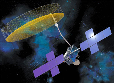
When TerreStar’s network is deployed, perhaps later this year, the company will provide universal access and tailored applications to millions of users throughout North America via mass market commercial wireless devices and spot beams.

TerreStar, which just announced $300 million in investor commitments through the launch of its hybrid mobile satellite, said Arianespace, the launch provider for TerreStar-1, has confirmed it can launch the satellite during the December 2008 through February 2009 launch window.

Competitor ICO also shares those MSS frequencies and boardchairman Craig McCaw would like to use ICO’s frequencies to carry mobile television as an adjunct to Clearwire’s Mobile WiMAX.

ICO plans to integrate its Mobile Interactive Media (MIM) suite of services with Clearwire’s broadband network. “Our next generation wireless personal broadband networks are built to deliver data, voice and video over a single network,” said Scott Richardson, chief strategy officer for Clearwire.

If Craig McCaw’s ICO can deliver live television to mobile DVB-SH receivers, who needs MediaFLO? Probably not Clearwire — or possibly Sprint’s Xohm. ICO’s first GEO satellite is scheduled to be launched in early 2008 with MSV’s hybrid service starting in 2009.

ICO’s G1 satellite is due to launch on an Atlas V launch next month by United Launch Alliance. ULA, by the way, is the product of a merged Evolved Expendable Launch Vehicle program (EELV) that stuck taxpayers with a $14.4 Billion bill for cost overuns due to Lockheed and Boeing’s duplicative rocket programs that ballooned from $17 billion to $32 billion in a few years.

Clearwire, a partner with Intel and Motorola, is committed to Mobile WiMAX, but I-HSPA handsets could be one option for AWS spectrum holders T-Mobile, Verizon and AT&T — featuring dual-mode AWS/satphone connections.


[get this widget]

Read More...
AddThis Social Bookmark Button

Mobile WiMAX at World Congress  

The WiMAX Forum today announced that 28 Mobile WiMAX products in the 2.3 GHz and 2.5 GHz frequency bands have been submitted for WiMAX Forum certification since WiMAX Forum labs began accepting applications from vendors in late 2007. The first Mobile WiMAX products are expected to achieve the WiMAX Forum Certified seal of approval in Q2 2008 and to reach the market later this year.

The organization also announced its official support for Mobile WiMAX certification in the 700 MHz band. Work on the technical specifications for 700 MHz WiMAX Forum certification is already underway in the association’s working groups. The published specifications will be unveiled as they are completed and they will support both TDD and FDD certification profiles.

“With more than 260 commercial WiMAX deployments rolled-out on a global basis, WiMAX technology is the only commercially available OFDMA-based wireless technology,” said Ron Resnick, president of the WiMAX Forum.

The WiMAX Forum media luncheon featured testimonials from global service providers, including Freedom4, Iberbanda, KDDI, Korea Telecom and SprintNextel and who each indicated the readiness of WiMAX technology with certified products and the optimization of WiMAX networks for broadband data services as key motivators in selecting WiMAX technology for their next generation services.

TelecomTV has video reports from Mobile World Congress 2008 (above).

Other WiMAX announcements at the big show in Barcelona:


[get this widget]

Read More...
AddThis Social Bookmark Button

Bare Nuckles in Barcelona: LTE Vrs WiMAX  

At the Mobile World Congress in Barcelona, the showdown pitting upstart Mobile WiMAX against Long Term Evolution, backed by heavy weight telcos, is going head-to-head. At stake is a huge global market for 4G telecom gear and services that could dwarf today’s 3G.

China Mobile announced today that it will join Verizon Wireless and Vodafone in a three-way operator trial of Long Term Evolution (LTE), the 4G mobile broadband standard, says Light Reading. China Mobile is the world’s largest mobile operator, with over 350 million customers, and may tip the 4G standards scales in LTE’s favor.

Along with Verizon and Vodafone, the operator joins the ranks of NTT DoCoMo, which has an aggressive LTE deployment plan and AT&T, which is expected to make a committment to LTE but has not made it official (yet).

Alcatel-Lucent also announced it is teaming with Japan’s NEC in a joint LTE venture. Alcatel-Lucent CEO Patricia Russo (left), said the move is an offensive play, rather than a defensive one.

“It’s about scale, time to market, and pooling existing R&D,” she told reporters during an afternoon press conference at the Mobile World Congress in Barcelona, Spain. “This is not a way to reduce our investment.”

The China Mobile trials will focus on both the frequency-division duplex (FDD) and time-division duplex (TDD) varieties of the LTE standard. The TDD version of LTE is China Mobile’s technology choice because it is an evolution of the Chinese homegrown 3G standard, TD-SCDMA.

LTE is a telecom-centric project. It is not a standard yet, but it is expected to mold the new release 8 of the UMTS IP-based standard. LTE’s overriding characteristic is many telco layers and proprietary protocols.

Most observers believe WiMAX has a 2-3 year lead over LTE.

That may have prompted GSM Association CEO Rob Conway to opine that WiMAX should become a subset of LTE.

WiMax supporters say it should be the other way around.

“We went from having virtually no products here in Barcelona last year to having over 40 companies with real products on their stands, so Wimax is here and it’s real,” said Wimax Forum president Ron Resnick.

Resnick said 28 Wimax products in the 2.3 GHz and 2.5 GHz frequency bands had been submitted for Wimax Forum certification since the forum’s labs opened for business late last year (pdf). The forum is aiming to certify 100 products for interoperability by the end of this year, and 270 by 2010 – not including CPE gear. The industry body, which lists almost 540 member companies, promoted a walking booth tour of over 40 companies at the show demonstrating Wimax equipment.

Cisco’s John Chambers predicted at the Mobile World Congress that by 2011, WiMax will account for 10 to 15 percent of wireless traffic.

GSMA chairman Craig Ehrlich has been openly critical of the Wimax business case, describing it as too little, too late in the face of escalating HSDPA rollouts and the coming of LTE. Officials at China’s MII attacked Wimax’s inclusion last October as an IMT-2000 standard, seeing it as a rival to their homegrown TD-SCDMA technology.

According to the GSM Association, about 80% of cellular users world-wide use the GSM (Global System for Mobile communications) technology, or more than 2.5 billion people. A total of 3.3 billion people — more than half the world’s population — now use cell phones. Revenues, which totaled $125Bn in 2007, are expected to reach $200Bn by 2011. Intel sees a $10 billion mobile chip market by 2011.


[get this widget]

Read More...
AddThis Social Bookmark Button

Footballer Gets Own 3G Mobile TV Channel  

Orange announced the launch of Frank TV, a mobile channel dedicated to England and Chelsea star Frank Lampard. Frank TV will be available exclusively to the 1.3 million Orange 3G customers on its mobile phone TV service - Orange TV, and will be up alongside other Orange mobile TV channels including BBC, Channel 4, Sky and FHM.
Frank TV features never-before-seen footage from Frank’s video diaries which he filmed over the past two seasons, giving exclusive behind the scenes access to Stamford Bridge, the Chelsea training ground, Frank’s house, pets and much more. There are also special guest interviews with Frank Lampard senior, Jamie Redknapp and Lawrence Dallaglio.

Jake Redford, Head of Mobile TV, Orange UK said: “We are delighted to launch a dedicated channel to arguably one of the most committed and professional midfielders in world football. Frank TV makes for great bite-size viewing and provides our mobile TV viewers unique insight to the life behind the footballer”.


[get this widget]

Read More...
AddThis Social Bookmark Button

Making the Case for 3G LTE - Global Mobile Broadband  

US : A new report published by the UMTS Forum predicts that LTE (Long Term Evolution) - Global Mobile Broadband could generate total revenues of €150 billion for operators by 2015.

The new report - titled Global Mobile Broadband: Market Potential for 3G LTE - forecasts that smooth evolution from today’s investments in 3G UMTS (WCDMA/HSPA) will kick-start a new wave of high-speed interactive services, strengthening ARPU in many mobile markets.

Specifically, the report predicts that subscriptions to LTE - Global Mobile Broadband networks will exceed 400 million by 2015, or double today's number of WCDMA/HSPA customers. Furthermore, revenues from LTE - Global Mobile Broadband will represent more than 15% of all mobile revenues that are predicted to approach €1 trillion globally in 2015.

While it's expected that Western Europe and developed Asia will account for the majority of LTE - Global Mobile Broadband customers, the report forecasts strong uptake in developing markets by 2015.

While non-voice services currently represent just 10-15% of revenues in developed markets, the study suggests that LTE - Global Mobile Broadband will drive this proportion to 36% by 2015.

The report is based on original research conducted for the UMTS Forum by Analysys Research (www.analysys.com), who modelled future demand for global mobile broadband by extrapolating current market trends.

With technical specifications for LTE now stabilised within the Third Generation Partnership Project (3GPP), it's an anticipated that the first LTE - Global Mobile Broadband networks will be commercialised in 2010. Wide-scale rollout is anticipated from 2011.

Building on current investments in the GSM/UMTS Evolution ‘family’ of 3GPP systems, LTE - Global Mobile Broadband provides a smooth evolutionary path to far higher data speeds and lower carriage costs with more efficient, flexible use of operators' radio resources.

With more than 165 HSPA networks already commercialised or in deployment, 3GPP’s significant global footprint will support a future mass market for high-speed, high capacity services at significantly lower cost than greenfield investment in other broadband wireless systems.

Enabled by SAE (Systems Architecture Evolution) that offers a 'flat' all-IP architecture, LTE - Global Mobile Broadband also promises lower latency that will support multiplayer gaming, social networking, high-quality videoconferencing and a new generation of other real-time interactive applications. The report also predicts that LTE - Global Mobile Broadband’s low latency and reduced per-bit costs will drive the development of remote monitoring and other machine-to-machine (M2M) applications.

"This new report demonstrates an extremely positive investment case for LTE - Global Mobile Broadband", comments UMTS Forum Chairman Jean-Pierre Bienaimé. "While it requires an upgrade of existing 3G infrastructures, dramatically reduced opex costs compared with WCDMA and HSPA could see operators break even as soon as 3-4 years after deploying LTE - Global Mobile Broadband."


[get this widget]

Read More...
AddThis Social Bookmark Button

LG Viewty Mobile Phone Enables Playback Video from the PC and the Internet  

LG and DivX announced their partnership to enable a high-quality consumer media experience with the LG Viewty (Model: LG-KU990), a new 5.0 mega-pixel digital camera phone available from LG Mobile.

The LG Viewty’s unprecedented multimedia capabilities reflect the extensive partnership between LG Electronics and DivX. The LG Viewty enables consumers to easily playback a wide range of DivX files from the PC on the go or output to a TV monitor without converting to another format. Consumers can also view DivX files from popular online video communities such as Stage6.com at ten times the speed of WCDMA through the HSDPA 3.6 high speed internet access capability. DivX is a widely popular digital media format that enables consumers to create, share and play back high-quality video content across an ecosystem of platforms and devices.

The super sleek and stylish LG Viewty is the first in LG’s new line of high technology handsets and boasts a number of ‘world first’ features never seen before on a mobile handset, including 120 fps video recording as well as unique camera functionality such as manual focus, image stabilizer and handwriting recognition that makes editing easy on the Viewty’s 3-inch wide LCD touch screen.

LG Viewty will go on sale from mid-October starting from Europe and on to other regions

[get this widget]

Read More...
AddThis Social Bookmark Button

Vodafone Neverfail High Availability Service for BlackBerry  

Europe : Vodafone UK announced that it has completed a deal with Neverfail, a leading global software company providing affordable continuous availability and disaster recovery solutions.

Vodafone will now offer business customers a high availability and disaster recovery service for mobile email using the Neverfail software.

In today’s business environment access to email whilst on the move is a key requirement for many organizations.

Losing email access, even for a short time, can have drastic consequences for businesses. The Vodafone Neverfail High Availability Service for BlackBerry will provide uninterrupted availability of BlackBerry services to Vodafone business customers.

The Vodafone Neverfail High Availability Service for BlackBerry monitors the health of the entire email environment, including the server hardware, the network infrastructure, the application and the operating system. If any anomalies are identified, Neverfail will immediately take action to prevent loss of service. It will either automatically attempt to restart applications before they fail, switch over to a secondary server, or alert the IT staff so that no downtime or loss of service is experienced. Once the issue is resolved, they are automatically switched back to the main servers and neither users nor administrators are required to restart their applications.
“As market leader in the UK in providing BlackBerry services, it was important to be able to offer robust access to email. By adding Neverfail’s solution into our Managed Service portfolio, we can offer enormous service expertise to protect critical parts of our customers’ IT infrastructure,” said Curt Hopkins, Head of Enterprise Mobility Solutions, Vodafone UK. “Neverfail has an enviable reputation for protecting mission-critical systems with its continuous availability solutions and we have selected them as our preferred provider for high availability and disaster recovery for BlackBerry and email implementations.”
“Vodafone as a company relies on continuous mobile access to email and we have also selected the Neverfail solution to use within our own organization,” continued Hopkins. “Having complete confidence that email will be available 24/7 365 days a year is a significant advantage as many key staff depend on access via Blackberry devices in order to fulfil their roles.”
“Vodafone is well ahead of the general telecommunications market. Rather than just providing handsets and airtime minutes, Vodafone is offering strategic services, such as high availability, to support the entire BlackBerry platform,” said Richard Ruddlesden, EMEA Channel Director, Neverfail. “We are very pleased that Vodafone has selected us to offer its customers an exceptional communications experience that is the best in the industry.”
Vodafone Managed Services will work in partnership with Neverfail in the UK to offer customers advanced capabilities such as continuous availability for mobile devices and communications solutions from RIM, MicrosoftÒ and IBMÒ LotusÒ NotesÒ.


[get this widget]

Read More...
AddThis Social Bookmark Button